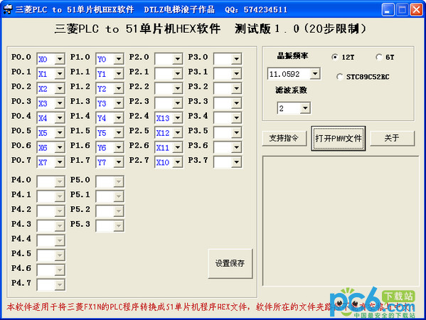


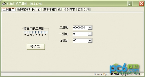
This software can convert the ladder diagram program written using Mitsubishi fxgpwin into a HEX format file that can be directly written to the microcontroller chip.
Although this software is mainly designed for the DKB-1A industrial control board, it also provides the Proteus (7.1 SP2 version) simulation file: gk.dsk. Friends who do not have hardware can try it with software simulation. You can also refer to the following instructions to build your own hardware for testing.
P2 and P0 are used as inputs. For P2, the input numbers are x0~x7, while P0 is X10~X17, and P1 is used as the output. Note that P1.7 is Y0 and P1.6 is Y1. . . By analogy, this is consistent with the DKB-1A hardware design.
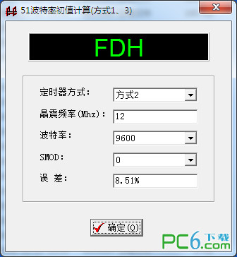
Use 12M crystal oscillator.
Category 51 chips cannot be used because the RAM and ROM of such chips are not large enough. Must use class 52 or a chip with more ROM and RAM.
Mitsubishi software writes the ladder diagram, then runs the conversion software, sets the input and output of the 51 microcontroller, opens the written ladder diagram, converts the hex file, and burns it into the 51 microcontroller, then the written PLC program can be executed.
Available resources:
t0~t15 100ms timers, 16 in total
c0~c15 total 16 counters
m0~m63 64 in total
s0~s63 64 in total
x0~x15 16 points in total
y0~y7 total 8 points
Support:
Program to support FX1N model of Mitsubishi PLC
When using programming software, please choose FX1N PLC
Hot search terms: 360 Security Guard Office365 360 browser WPS Office iQiyi Huawei Cloud Market Tencent Cloud Store


Useful
Useful
Useful