-
Electrical EngineerCAD
- Size: 174.41M
- Language: Simplified Chinese
- Category: CAD software
- System: winall


Electrical Engineer CAD2010It is a general electrical engineering design software package developed based on the latest electrical design specifications and adopting the suggestions of many engineers. It is based on AutoCAD2010 and fully adopts ARX technology. Electrical Engineer CAD2010 includes schematic design, system diagram design, wiring diagram design, electrical construction drawing design, electrical floor plan design, a new graphic symbol library, electrical design calculations, equipment statistics, chart generation, dimensioning and text table processing and other functions. Electrical Engineer CAD2010 has powerful functions, rich libraries, Chinese interface, and is easy to learn and use. I believe it will definitely bring great help to your design work. Huajun Software Park provides the download of CAD2010 for electrical engineers. Friends who need it can download it quickly!
Screenshot of CAD installation interface for electrical engineers
Introduction to CAD2010 functional features for electrical engineers
1. Flexible and efficient schematic design
Electrical Engineer CAD provides a powerful schematic drawing function. Whether you are drawing a new schematic or modifying an existing drawing, you will be able to do so easily, quickly and accurately. This software can insert single or multiple components in the circuit very conveniently and flexibly. The inserted components can be moved, aligned, flipped, mirrored, scaled, copied, replaced, interchanged, deleted, removed, labeled, etc. It can also modify the color, line width, etc. of the components. This software also provides functions for quickly drawing and editing wires, such as: single wire, a group of wires, polyline, multi-point connection drawing, wire connection, group wire connection, wire extension, wire intersection, wire branch and other editing functions. This software also provides basic system diagrams, control system diagrams, power distribution system diagrams, lighting system diagrams, power system diagrams, power supply system diagrams, antenna system diagrams, motor main circuits, transfer switch closure tables and other design modules.
2. Professional and practical wiring diagram design
CAD for electrical engineers provides the functions of drawing round terminals, rectangular terminals, fixed terminals, detachable terminals, drawing terminal lead wires, adding lead wires and component wiring marking functions, providing the functions of drawing terminal strips, filling in terminal strips, and providing drawing tests The functions of terminals, connecting terminals, contact terminals, special terminals, grounding terminals, fuse terminals, and breakable terminals provide functions such as drawing cables and cable connections, arrow connections, drawing branch lines, drawing a set of parallel conductors, and connecting two sets of conductors.
3. Powerful floor plan design
Electrical Engineer CAD provides a variety of equipment layout methods, such as arbitrary layout, straight line uniform distribution, arc uniform distribution, rectangular uniform distribution, through-wall layout, etc. The equipment layout is dynamically displayed, and what you see is what you get. It also provides editing tools such as equipment uniform distribution, move, mirror, flip, zoom, copy, replace, swap, move out, delete, change color, line width, horizontal positioning, vertical positioning, alignment and arrangement, etc., which can meet the needs of floor plan design. Various layout requirements for timing; It provides floor plan wiring functions, such as general wiring, wall wiring, parallel wiring, drawing parallel lines, a set of equipment connections, equipment wiring, power distribution leads, lightning protection wires, grounding wires, broadcast wires, TV wires, etc. It also provides editing tools such as wire placement up, wire placement down, wire interruption and merging, and corner pulling; in addition, parameterized libraries for motors, transformers, towers, 04kV poles, etc. are provided. It also provides functions such as pebble filling, wire marking, lamp marking, switch marking, equipment marking, and wire number marking.
4. Brand new graphic symbol library
The library management module provided by Electrical Engineer CAD can easily classify, query, browse, call and expand the symbol library; the library interface is flexible and free, can be automatically rolled and opened, and the window size and position can be adjusted at will, which is a user-friendly design. Symbol classification is professional and rich in content. The majors involve machine tool electrical, building electrical, switch cabinets, factory design and other fields, including switches, lamps, sockets, strong (weak) electrical equipment, HVAC, air conditioning, cable TV, network communications, broadcasting, security, fire protection, power, thermal engineering, refrigeration, chemical industry, pipelines, hydraulics, pneumatics, machinery, etc.
5. Dimensioning and text table processing
Electrical Engineer CAD provides powerful dimensioning functions such as horizontal, vertical, tilt, angle, diameter, radius, coordinates, and a set of linear dimensions. At the same time, this software provides a wealth of dimension editing tools, such as dimension alignment, dimension equal spacing, etc. Using this software, you can easily modify text content, text alignment, text equal spacing, merge two lines of text, modify text height, aspect ratio, font type, add underline, overline, diameter symbols, plus and minus signs, angle symbols to text, draw any table, drag the table, fill in the table, fill in a group of text, center the table text, copy the table text, etc.
6. Graphics processing capabilities
Electrical Engineer CAD can automatically block the two graphics in the picture and determine whether to use dotted lines to represent the blocked parts; dimension text can also block the graphics. A break line breaks a shape in the middle. This software can also automatically partially enlarge graphics within a certain boundary, and also provides powerful mathematical calculation functions.
7. Perfect frame drawing and title block filling
Electrical Engineer CAD provides a frame drawing module that fully complies with national standards. At the same time, users can also generate frames with custom sizes. The software provides several commonly used title bars and additional columns. Users can easily define the title bar and additional columns of their unit (the height of the text filled in the columns can also be defined by the user). The contents of the title bar and additional columns can be entered in the dialog box very conveniently, and the entered content will be automatically filled in the picture frame. User-defined title bars and additional columns can also be filled in automatically. After the picture frame is inserted, the user can also replace the existing picture frame with a new picture frame. The position and text height of the replaced title bar, additional column and filled-in content will be automatically adjusted. Data in one frame can also be automatically filled in to another frame.
8. Advanced parameter-driven library
CAD for Electrical Engineers provides a parameter-based size-driven library system that can quickly draw cable pits, transformers, poles, and iron towers of various structures; it also provides a standard parts library for mechanical and chemical engineering majors.
9. Comprehensive architectural design module
CAD for electrical engineers provides powerful architectural design functions, including linear axis grids, arc axis grids, straight walls, arc walls, round walls, doors and windows, columns, balconies, single-run stairs, double-run stairs, curved stairs, elevator insertion, etc.
10. Adopt Chinese interface, carefully designed, complete functions, easy to learn and use
The CAD commands for electrical engineers are all abbreviations of the first letters of Chinese Pinyin. Each menu has one or several toolbars corresponding to it. The corresponding toolbar can be found from the corresponding menu. The software uses the most common terminology used by designers, and the usage method is completely in line with professional design habits, so it is easy to master, and even beginners can master it in a short time.
11. Electrical Engineer CAD is fully compatible with AutoCAD 2002/2004/2005/2006/2007/2008/2009/2010 Chinese and English versions
"Electrical Engineer CAD 2010" is fully compatible with the Chinese and English versions of AutoCAD 2002/2004/2005/2006/2007/2008/2009/2010, instead of being limited to a certain version or only the Chinese or English versions, allowing you to be worry-free and easily engaged in design in any environment and situation. For other non-DWG format graphics, this software can read them in DXF format.
12.Electrical EngineerCADSystem requirements
Simplified Chinese NT4.0/2000/XP/2003/VISTA operating system; AutoCAD2002, 2004, 2005, 2006, 2007, 2008, 2009, 2010 versions supported. Pentium III or above processor, 512 MB or above memory, 1024 x 768 VGA monitor, more than 500 MB hard disk space, 4x or above CD-ROM drive.
How to use CAD 2010 for electrical engineers
How to open and create a new dimension style manager in Electrical Engineer CAD 2010:
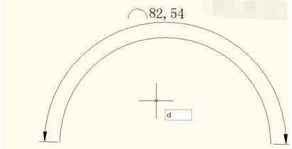
1. Take this as an example, enter d directly on the interface and press space to confirm.
2. The style annotation manager will open, and it will look like this.
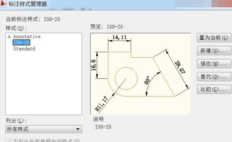
3. Then start creating a new one.
4. Modify the style name, write one yourself, and then click Continue.
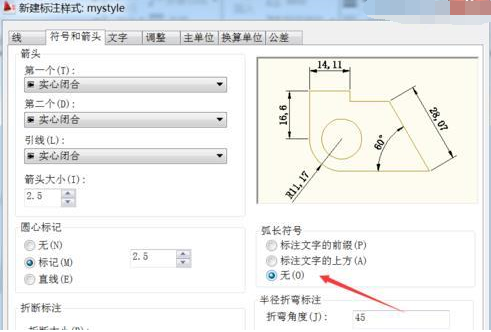
5. Here are all the styles. You can set them as you like. We will simply set the arc length symbol and set it to None. Then click OK and close.
6. Then click on the arc length mark, and then select our own new one in the style. The style will change.

7. The symbol in front of the arc length is gone, so we can set various styles through this.

Version: 2010 Enterprise Edition | Update time: 2024-12-23
Similar recommendations


Latest updates


How to create temporary blocks in CAD 2010 for electrical engineers?
How to set hatch island style in CAD 2010 for electrical engineers
Tutorial on how to use the fixed number equal division function in CAD 2010 for electrical engineers
How to mark the radius and diameter of a circle in CAD 2010 for electrical engineers
How to open and create a new dimension style manager in CAD 2010 for electrical engineers
How to add custom hatch graphics in CAD 2010 for Electrical Engineers
115How to change the network name in the browser? -115 Methods to modify network name in browser
How to import audio in scratch-How to import audio in scratch
How to add characters to scratch-How to add characters to scratch
CAD Review for Electrical Engineers
-
1st floor Huajun netizen 2015-07-10 11:50:24CAD is very useful for electrical engineers, thank you! !
-
2nd floor Huajun netizen 2018-10-26 19:56:09The CAD interface design for electrical engineers is easy to use and has rich functions. I highly recommend it!
-
3rd floor Huajun netizen 2021-05-27 18:59:31The overall feeling of the electrical engineer's CAD is good and I am quite satisfied. The installation and operation are very smooth! It went very smoothly following the installation step-by-step instructions!
Recommended products


- Diablo game tool collection
- Group purchasing software collection area
- p2p seed search artifact download-P2P seed search artifact special topic
- adobe software encyclopedia - adobe full range of software downloads - adobe software downloads
- Safe Internet Encyclopedia
- Browser PC version download-browser download collection
- Diablo 3 game collection
- Anxin Quote Software
- Which Key Wizard software is better? Key Wizard software collection