-
Cadence Allegro
- Size: 3102.72M
- Language: Simplified Chinese
- Category: Mechatronics
- System:winall


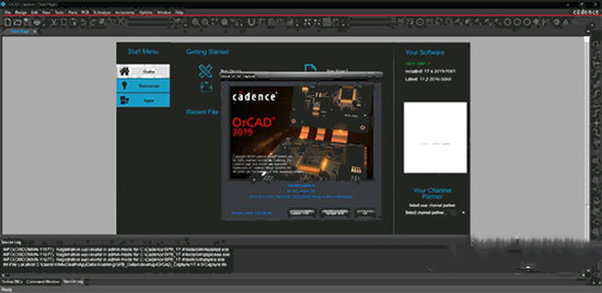
Cadence Allegro Chinese version is a powerful PCB circuit design tool. Cadence Allegro official version provides users with almost all electronic design processes, with high-speed, high-density, multi-layer complex PCB design and wiring functions. by Cadence Allegro software users can perform parameter scanning analysis and statistical analysis, which improves the efficiency of schematic design.
Cadence Allegro software introduction
Cadence’s electronic design automation products cover the entire electronic design process, including system-level design, functional verification, IC synthesis and layout and routing, analog, mixed-signal and RF IC design, fully customized integrated circuit design, IC physical verification, PCB design and hardware simulation modeling, etc. At the same time, Cadence also provides design methodology services to help customers optimize their design processes; it also provides design outsourcing services to assist customers in entering new market areas. Since 1991, the company has continuously ranked first in sales performance in the international EDA market. The world's leading semiconductor and electronic systems companies use Cadence software as their global design standard.
What's new in Cadence Allegro
1. Comparison of design differences
When there are differences between the two circuit diagrams, use Capture Compare Design The function allows you to choose to compare the differences between circuit diagram folders or circuit diagram drawing pages. The comparison results can be used to view the differences in circuit diagram logic or graphics.
In the Capture menu, select the Tools Compare Designs function menu to compare the differences in the circuit diagrams.
2. Advanced part number arrangement function (Advanced Annotation)
In Capture A new function of advanced part number arrangement has been added. In this function, you can set different starting serial numbers for different circuit diagram drawing pages, and you can also set different starting serial numbers for different parts on the same page of circuit diagram drawings.
3. Add new personal working environment settings
OrCAD Capture now has a more advanced setting interface for user environment settings. Use Option Preference More in the function menu. Preference enters the setting interface. In the new Extended Preferences Setup, you can make advanced settings for the following environments:
1. Command Window (Command Shell)
2. Design and Libraries
3. Design Cache
4. Design Rule Check (DRC)
5. OrCAD Capture CIS (CIS)
6.Network Group (NetGroup)
7. NetList
8. Circuit diagram (Schematic)
4. Browse sample designs
In the Cadence 17.2-2016 software installation directory, more than 150 sample files are integrated and provided so that users can quickly understand and learn OrCAD Design of Capture, OrCAD Capture CIS, and OrCAD Capture–OrCAD PSpice design processes. In OrCAD Capture In 17.2-2016, you can simply open the built-in sample file through the function menu of File – Open – Demo Design.
5. Output and input of file formats
OrCAD Capture uses File – Export – Design XML or Library XML commands and File –Import –Design XML or Library XML Command, you can output the circuit diagram and parts library to XML through the toolscapturetclscriptscapdbdsn.xd and olb.xd programs in the program installation directory. format, and reload the XML format into a standard circuit diagram and parts library.
6. Intel Schematic Export Format (ISCF) format output
OrCAD Capture can use the File –> Export –> ISCF interface for circuit diagram parts, pin attributes and ground signal output Intel Schematic Export Format (ISCF) format. This format can set the output of parts or part pin attributes through the user interface. After output, these settings will be archived in Caputre.ini file so that it does not need to be reset for next time use.
Cadence Allegro usage tips
1. The difference between regular pad, anti-pad and thermal pad
a: Real pad size, isolation size pad, flower pad
2. How to make a square (or other non-circular) negative thermal disk?
a: Make a square (or other non-circular) shape symbol, and then assign the shape symbol to flash when making pad~~
3. I want to move a certain pin of the component. How to do it? When using the move command, it always prompts symbol or drawing must have unfixed_pins property.
a: edit -> properties Select the symbols of the component to be moved pin and add the unfixed_pins attribute.
4. How can I get rid of the "dynamic length" dialogue box?
a: setup -> user preferences editor ->etch>allegro_etch_length_on
5. How can I restore the deleted pin number and silkscreen?
a: Delete this part and re-import it~~~or you can update the part directly
6. After importing from Orcad, go to place->quickplace, but there are many wires on the components that come out, just like laying copper. What's going on?
a: Just uncheck place_bound_top of package geometry.
Cadence Allegro update log
1: Brand new interface, refreshing, simple and efficient
2: Performance is getting better and better
Huajun editor recommends:
Cadence Allegro has the same complete functions as the official product, the interface is more beautiful and elegant, and the design is more complete. It continuously meets the needs of users. Welcome to download. If you are interested, you can also download Cruzr, .NET, and Cloud Machine Manager
Version: 16.6 | Update time: 2024-12-31
Similar recommendations


Latest updates


How to input Chinese in scratch-How to input Chinese in scratch
How to fire bullets in scratch-How to fire bullets in scratch
How to draw a fan with scratch-How to draw a fan with scratch
How to create arrows in scratch-How to create arrows in scratch
How to set the windmill rotation in scratch-How to set the windmill rotation in scratch
How to draw a spiral in scratch - How to draw a spiral in scratch
How to create a ray background in scratch-How to create a ray background in scratch
How to draw a timer in scratch - How to draw a timer in scratch
115How to set up automatic login in the browser? -115 How to set automatic login in browser
Cadence Allegro Review
Recommended products
-

Electrician simulation teaching software
-

eplan electric p8
-

proteus7.8
-

Machining CNC milling machine simulation software
-

LedshowTV2021 (LED display control editing software)
-

RegalIgs
-

Mitsubishi PLC learning software (FX-TRN-BEG-C)
-

AutoCAD Electrical
-

CNC machine tool simulation software
-
Tianyi Computer Industry Edition
- Diablo game tool collection
- Group purchasing software collection area
- p2p seed search artifact download-P2P seed search artifact special topic
- adobe software encyclopedia - adobe full range of software downloads - adobe software downloads
- Safe Internet Encyclopedia
- Browser PC version download-browser download collection
- Diablo 3 game collection
- Anxin Quote Software
- Which Key Wizard software is better? Key Wizard software collection