At present, some partners have just started using the powerdesigner software. When operating it, they may not know the relevant operations of drawing ER diagrams. So how do you draw ER diagrams using powerdesigner? The specific steps are explained below.
Open the powerdesigner software.
Select File-->New, a dialog box will pop up, and select the CDM model (i.e., conceptual data model) to build the model.
Complete the creation of the conceptual data model.
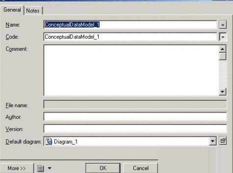
Select the newly added CDM model, right-click, select the "Properties" attribute item in the pop-up menu, and a dialog box will pop up. In the "General" tab, you can enter the name, code, description, creator, version, default chart and other information of the created model. Relevant description and explanation information can be entered in the "Notes" tab. For more tags, click the "More>>" button.
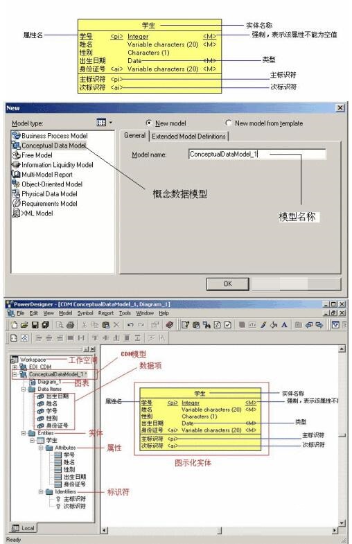
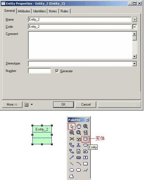
In the CDM graphics window, click the Entity tool on the tool options panel, and then click on a blank space in the graphics window. An entity symbol will appear at the clicked position. Click the Pointer tool or right-click the mouse to release the Entitiy tool.
Double-click the newly created entity symbol to open the following icon window. In the "General" tab of this window, you can enter the entity's name, code, description and other information.
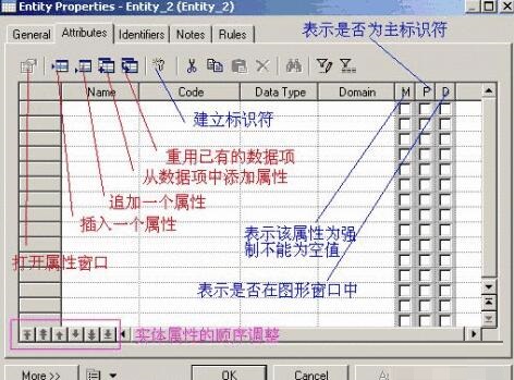
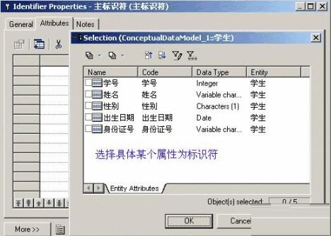
Attributes can be added on the "Attribute" tab of the above window. Click the Insert Property button to bring up the properties dialog box.
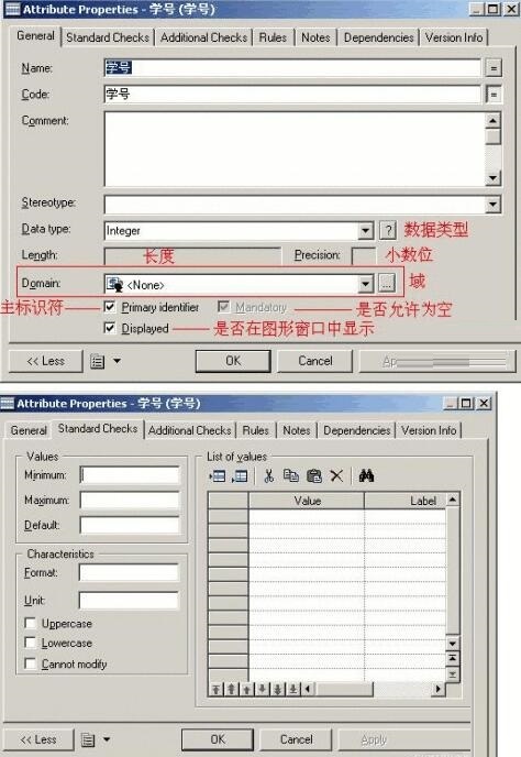
A standard check constraint is a set of expressions that ensures that a property is valid. In the Properties window of the entity properties, open the Inspection tab as shown.
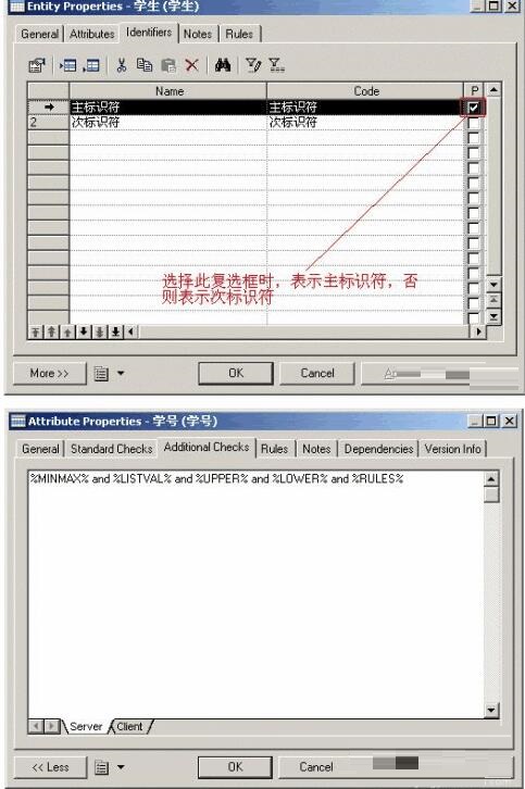
When Standard checks or Rules cannot meet the requirements of the check, you can use the %MINMAX%, %LISTVAL%, %RULES%, %UPPER%, and %LOWER% variables in the SQL statement to define Standard and Rule on the Server subpage of the Additional Checks tab.
Above, I have shared with you the specific steps for drawing ER diagrams with PowerDesigner. Friends in need should hurry up and read this article.