Don’t you know how to use CAD Viewer to mark angles? In fact, it is not difficult. Below, the editor will share with you the method of CAD Viewer to mark angles. Friends in need can come and take a look. I hope it can help everyone.
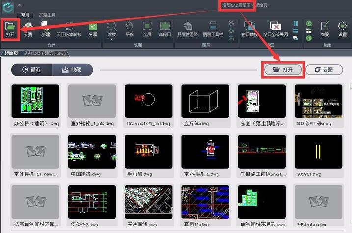
First, open the drawing in CAD Viewer.
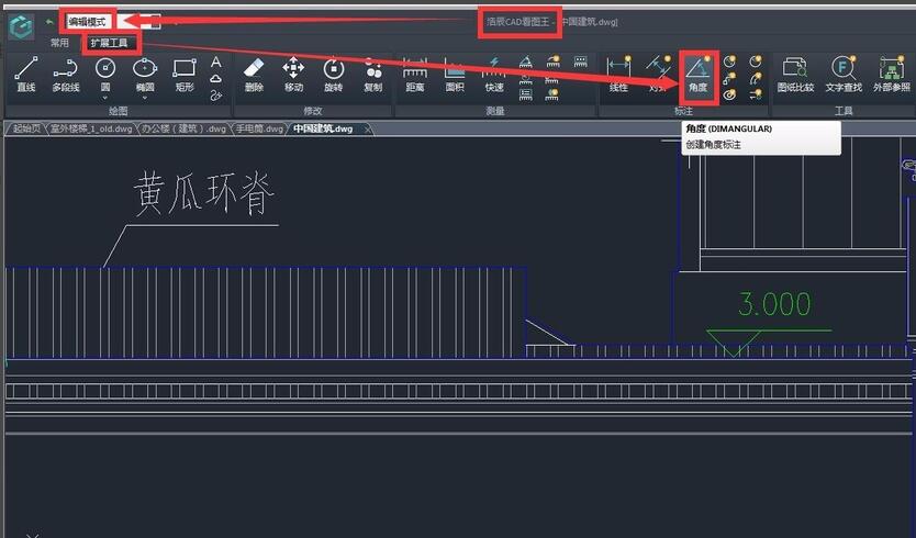
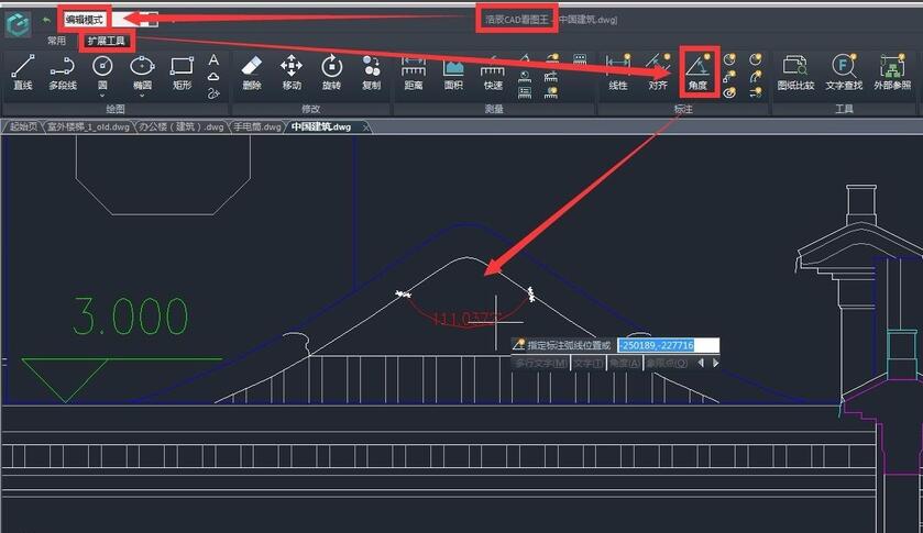
In edit mode, select the angle dimension function in the extended toolbar.
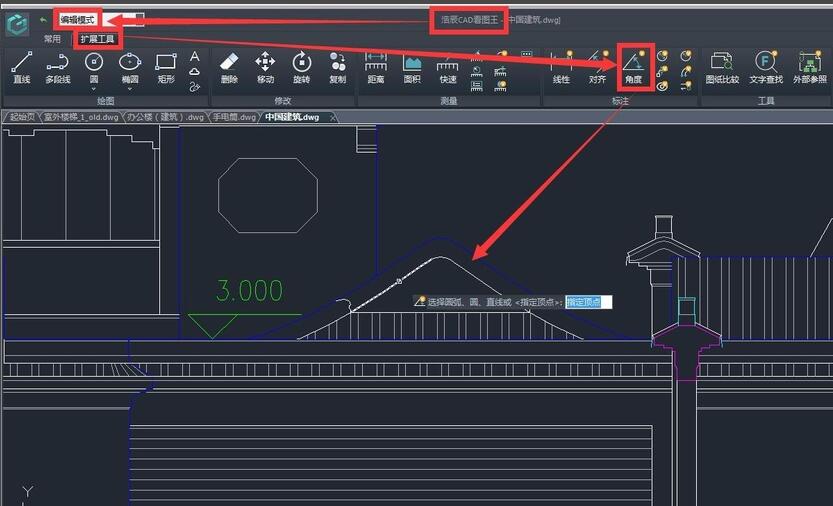
Click the left mouse button to locate the starting point of the label, that is, specify the arc, circle, straight line, etc. of the first side of the label angle.
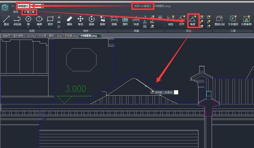
Drag the mouse to the positioning end point and click the left mouse button to specify the arc, circle, straight line, etc. of the second side of the dimension angle.
Drag the mouse to the end point of the label, click the left mouse button to complete the label, that is, specify the label arc position.
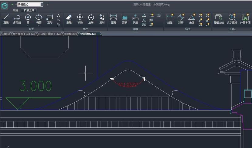
The completed annotation result is as shown in the big red part in the picture below:
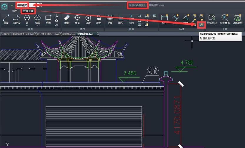
It should be noted that the annotation measurement settings can be made in the CAD Viewer PC version. If the font size, proportion, unit and accuracy of your annotations are not what you want, you can modify them in the annotation measurement settings. The location of the annotation measurement settings is as shown in the figure below:
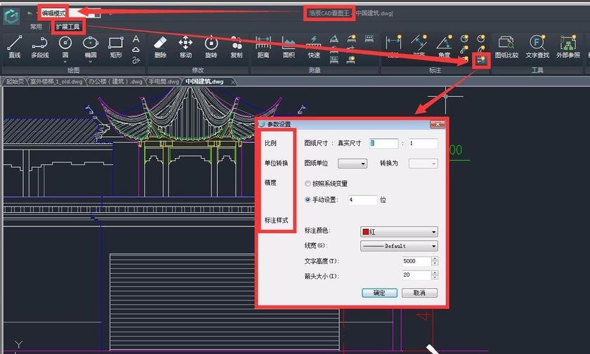
After clicking, the parameter setting dialog box will appear. In the dialog box, we can set the scale and precision of the label as needed, as well as the label color, line width, text height and arrow size in the label style. We can also convert the units to achieve the labeling results we want.
The above is the method of angle annotation shared by the editor in CAD Viewer. Friends who don’t know how to do it should hurry up and learn it.